




How to Get Primerless Vacuum Metallization Right with BMC Resin
Primerless vacuum metallization on BMC needs four things: a metallization-grade BMC resin, a properly prepared surface, controlled vacuum and PVD process settings, and proven adhesion testing. Headlight makers choose this method for clear reasons. It removes a coating step, cuts VOC emissions, and lowers the cost per part. Skipping primer works only when every part holds together. Each requirement depends on the others. A weak resin formula ruins the best surface treatment. Poor chamber control spoils a clean substrate. A gap in any one area shows up as poor adhesion or visible defects. This guide gives step-by-step technical help on material selection, surface preparation, process settings, quality testing, and defect troubleshooting.
Key Takeaways
Pick a BMC resin that has low styrene and cures fully. This helps prevent gas bubbles and weak adhesion.
Use plasma and micro-etching to clean and activate the surface instead of using a primer.
Keep the chamber pressure, plasma power, and deposition rate under control. This gives you strong adhesion and bright reflectivity.
Check every lot with tape, cross-hatch, and thermal cycling tests to make sure the coating holds.
Find where problems like haze or blisters come from, then fix that exact cause.
BMC Resin Properties for Metallization
Formulation and Surface Chemistry
The base bmc resin formulation decides how a part acts inside the vacuum chamber. Styrene content matters most. A high leftover styrene level means the compound gives off volatile organic molecules during pump-down and deposition. These molecules settle on the substrate and compete with the aluminum layer. The result is weak adhesion and a cloudy finish. Formulators therefore aim for a low leftover styrene level and a complete cure. A fully cured bmc resin gives off very little gas, so the deposited aluminum bonds right to the polymer surface.
Cure degree needs just as much attention. Under-cured parts keep reactive groups near the surface. These groups move during plasma treatment and disturb the interface. Over-cured parts turn brittle and may crack under thermal load. Processors should check the cure with a glass transition test before metallization. A steady cure window gives a stable surface chemistry, and stable chemistry gives repeatable adhesion.
Filler and Fiber Effects
BMC is a bulk molding compound, and it must flow quickly into the mold before early crosslinking starts. Slow or uneven filling traps air and creates flow marks. Both defects carry into the metallized part as visible haze. Steady molding, with controlled temperature and injection speed, makes a dense, uniform skin. That skin is the base for a mirror-grade reflective surface.
Filler type and fiber content shape how smooth the surface is. Coarse calcium carbonate fillers and long glass fibers sit close to the surface and scatter light. Fine fillers and well-wetted fibers leave a smoother skin. Low-shrinkage additives cut cure shrinkage and limit sink marks and waviness. A low-shrinkage system keeps the surface flat, so the aluminum coating reflects evenly. Processors should match filler grade and fiber loading to the required reflectivity class, then check the surface before committing to production.
Primerless Surface Preparation
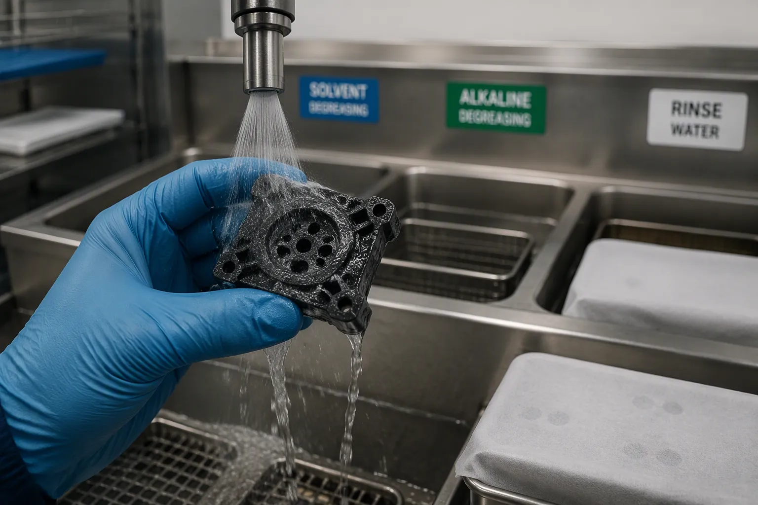
Mold release agents, fingerprints, and dust in the air all rest on a newly molded part. Each one blocks the bond between the aluminum layer and the base material. Primerless metallization takes away the primer coat, so the cleaning step must handle all contamination control. A part that passes cleaning must show an even water-break film. Water should spread evenly across the surface, not form beads. Beading means oil or silicone residue is present, and that residue will cause adhesion loss later. Processors should run the water-break check on a scrap part from each shift before starting production.
Cleaning and Degreasing
Solvent cleaning comes first. Processors wipe or dip parts in a solvent bath that dissolves release agents and machining oils. The solvent must be fresh or checked for contamination. A used-up bath just spreads residue across the surface. Alkaline degreasing follows for heavier soils. An alkaline bath breaks down oils and lifts particulate matter. Temperature and concentration need control, because a weak bath leaves a film and a strong bath attacks the resin surface. Rinsing with deionized water removes the alkaline residue. Drying follows right away, since trapped moisture becomes a gas source in the chamber.
Handling controls protect the clean surface. Operators wear clean gloves and handle parts by masked edges only. Bare-hand contact leaves skin oils that survive most cleaning steps. Parts move from cleaning to the vacuum chamber in covered trays. Any delay in a humid room invites moisture pickup, and moisture releases gas during pump-down. A written cleaning sequence, with bath life limits and glove rules, keeps results repeatable from batch to batch. Processors should also check the compressed air used for blow-off, because oil carryover from a compressor contaminates a clean part in seconds. A set hold time matters too. Parts that sit overnight collect dust and moisture, so scheduling should keep the gap between cleaning and coating short.
Surface Activation and Micro-Etching
Cleaning removes contamination. Activation raises surface energy so the aluminum layer wets and bonds. Plasma treatment does this job without a primer. A low-pressure gas plasma, usually oxygen or an argon-oxygen mix, hits the surface with energetic ions. These ions break polymer chains and attach polar groups to the surface. Surface energy rises, and the bmc resin surface becomes ready to receive the deposited metal. Plasma also removes the last traces of organic residue. Treatment uniformity matters as much as treatment strength. Shadowed areas and part fixtures can block the plasma, so rack design should expose every reflective face to the glow.
Micro-etching adds mechanical grip. A controlled etch, applied in the same plasma chamber or as a wet step, opens micropores in the resin-rich skin. The deposited aluminum locks into these pores and forms a mechanical anchor. Etch depth must stay shallow. An over-etched surface turns chalky and scatters light, which ruins reflectivity. Processors should tune plasma power and treatment time to the specific bmc resin grade, then confirm the result with a water-contact-angle check or a tape adhesion test on a coupon. Activation and etching work as a pair. Plasma raises chemical bonding, and micro-etching adds physical grip. Together they replace the primer layer and deliver the adhesion that headlight service conditions demand.
Vacuum Metallization Process Parameters
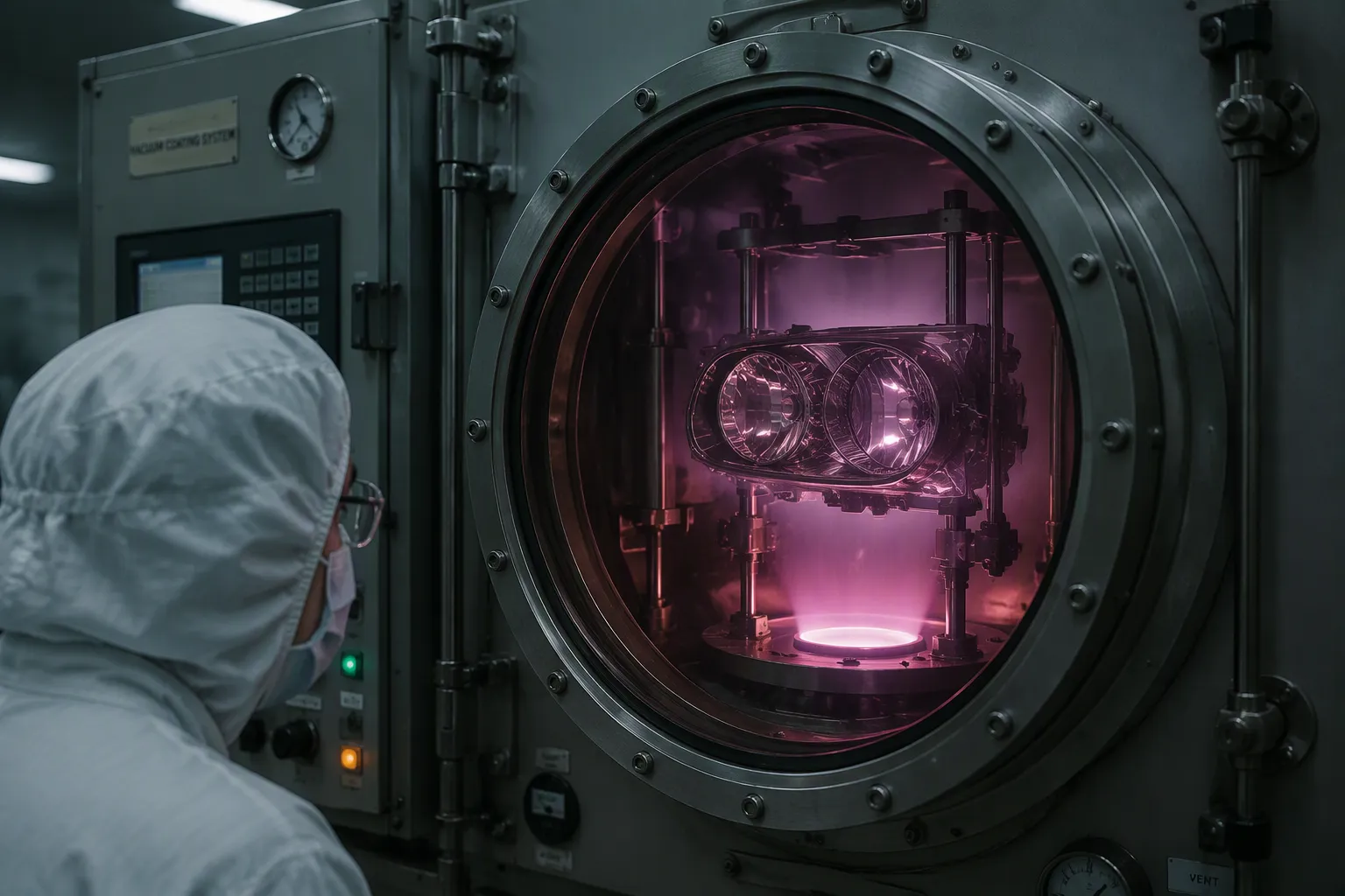
Vacuum metallization is a PVD coating process. A metal source, usually aluminum, turns into vapor under low pressure. It then condenses on the part as a thin reflective film. Headlight reflectors depend on this film for optical performance. Functional parts depend on it for barrier and decorative properties. The process window decides both adhesion and reflectivity. Three levers control that window: chamber pressure, plasma power, and deposition rate.
Plasma Treatment and Chamber Settings
Chamber pressure sets the mean free path of the plasma species. If pressure is too high, ions scatter before they reach the surface, so activation weakens. If pressure is too low, the glow starves and treatment slows. Processors should pump the chamber down fully before adding the process gas. Leftover moisture and volatiles from the bmc resin compete with the working gas. A clean, dry chamber gives a stable glow and a repeatable surface energy.
Plasma power controls how much energy hits the part. Higher power raises surface energy faster and burns off organic residue. But too much power etches the resin-rich skin and creates a chalky layer that dulls the finish. Rack design matters here. Fixtures must expose every reflective face to the plasma glow, and shadowed zones will show weak adhesion later. Processors should qualify a power and time recipe for each part geometry, then lock it. A dimensionally stable substrate helps, because a part that warps in the chamber changes its distance to the electrodes and gets uneven treatment. POLYMER's SMC & BMC Compounds offer low shrinkage and dimensional stability, which suits surface-sensitive automotive parts such as reflectors and housings.
Aluminum Deposition and Thickness
Deposition rate balances speed against film quality. A fast rate builds thickness quickly but produces a coarse grain structure that scatters light. A slow rate gives a dense, smooth film with high reflectivity, but it costs cycle time. Processors should tune the rate to the required optical class and confirm it with a reflectance check on a coupon.
Film thickness follows the same logic. A film that is too thin leaves gaps and shows the substrate through the coating. A film that is too thick builds stress and may craze or lift under thermal load. Thickness uniformity across the part depends on source-to-part distance and part rotation. Processors should rotate the rack and map thickness at several points, not just the center. Aluminum gives the brightest finish, and a tight thickness band keeps color and reflectance consistent from batch to batch. Chamber pressure during deposition also affects film density, so pressure and rate should be tuned together rather than one at a time.
Quality Control and Adhesion Testing
Adhesion and Durability Tests
A metallized headlight reflector must keep its coating through years of heat, cold, and vibration. Testing begins with the tape test. An operator presses a strip of special adhesive tape onto the coated surface, smooths it down, and pulls it off at a steady angle. Any aluminum that comes off on the tape means the bond is weak. The cross-hatch test goes a step further. A cutter scores a grid pattern through the film, and the operator puts tape over the grid. How much coating stays behind grades the adhesion, using the scale in ASTM D3359. Both tests are fast and destructive, so they run on coupons or scrap parts from each production lot. A clean pull with no coating loss sets the pass line. The operator writes the result on a lot card, and a failed lot goes back for process review before shipment.
Thermal cycling copies real service. Parts move between hot and cold extremes in a chamber, then come back to room temperature for another tape check. A coating that survives cycling without blistering or lifting has passed the hardest test. Humidity exposure adds another check, because moisture attacks the bond between the aluminum and the bmc resin. Vibration testing completes the program for parts that face road load. POLYMER's SMC & BMC Compounds offer low shrinkage and dimensional stability, so test coupons match production parts closely and results stay repeatable.
Cosmetic Inspection Criteria
Visual inspection catches what adhesion tests cannot. Inspectors check reflectivity under controlled lighting and look for haze, pinholes, flow marks, and color shift. A defined limit sample set guides the judgment, so every inspector grades against the same reference. Consistent surface appearance from the substrate makes this grading reliable. POLYMER's SMC & BMC Compounds deliver consistent surface appearance, which supports repeatable inspection results across batches. Inspectors also check masked edges and mounting features, since coating buildup there can disturb fit.
Troubleshooting Common Defects
Adhesion Failures and Blistering
Adhesion failures usually come from contamination or surface activation that did not finish. If a part passes the tape test on one face but fails on another, a shadowed zone in the plasma rack is the likely cause. Operators should first map where the failure is, then check fixture coverage. Failures spread across the whole part point to a cleaning problem instead. A used-up solvent bath or a skipped rinse leaves a film that blocks bonding. Processors should pull a scrap part and run the water-break check again.
Blistering takes a different path. Trapped moisture or leftover styrene boils off under vacuum and pushes the film away from the surface. The cure degree of the bmc resin deserves a check here. An under-cured part holds volatiles that release slowly during pump-down. Extending the pump-down time or adding a bake-out step before deposition often clears the problem. Blisters that show up only after thermal cycling point to a thick film under stress, so the deposition recipe needs review.
Haze, Pinholes, and Uneven Reflectivity
Haze dulls the mirror finish and scatters light. Over-etched surfaces turn chalky, and coarse filler sitting near the skin scatters light the same way. Inspectors should compare the part against the limit sample set and trace the haze to its source. A uniform haze across the part suggests plasma power is too high. Localized haze near the gate suggests a molding flow problem.
Pinholes come from dust, outgassing, or spitting from the aluminum source. Operators should check the chamber for debris and confirm the source is properly conditioned. Uneven reflectivity across a large part usually means the rack geometry is wrong. Source-to-part distance and rotation speed control film uniformity. Processors should map reflectance at several points and adjust the rack before touching the deposition rate.
Primerless vacuum metallization succeeds through a fixed sequence of steps.
Select a metallization-grade bmc resin with low outgassing and a complete cure.
Clean, activate, and micro-etch the surface to replace the primer.
Optimize chamber pressure, plasma power, and deposition rate for adhesion and reflectivity.
Verify results with tape, cross-hatch, and thermal cycling tests plus cosmetic inspection.
Trace any defect to its source and correct it with a targeted action.
Each step protects the next. A shortcut in one area shows up as a failure in another. When material, surface, and process stay under control together, primerless metallization becomes an achievable and repeatable production method.
FAQ
Does primerless metallization hold up as well as a primed system?
A primerless process that is well controlled meets the same service demands as a primed one. Adhesion depends on surface energy and a clean interface, not on the primer itself. Plasma activation and micro-etching create that interface. Parts that pass tape, cross-hatch, and thermal cycling tests show the bond is sound. The key is keeping cleaning and chamber control strict.
How can a processor tell whether a BMC grade suits metallization?
The grade should show low leftover styrene, a complete cure, and a smooth resin-rich skin. Processors should ask the supplier for outgassing data and surface appearance samples. A trial run on coupons confirms the behavior before production. POLYMER's SMC & BMC Compounds offer low shrinkage and consistent surface appearance, which supports this evaluation.
Can an existing primer line convert to primerless operation?
Yes, with changes to cleaning and surface treatment. The primer booth comes out, and plasma activation becomes the critical step. Operators need new rack designs that expose every reflective face to the glow. Cleaning controls get tighter, because no primer coat hides contamination anymore. Processors should qualify the new recipe on scrap parts before running production.
What causes batch-to-batch variation in adhesion results?
Variation usually comes from three sources: cure degree drift, contamination in the cleaning baths, and plasma chamber conditions. A shift in molding temperature changes the surface chemistry. A used-up solvent bath leaves residue. A dirty chamber weakens the glow. Processors should log cure checks, bath life, and chamber cleaning on every lot and compare results against the tape test record.
How should a processor handle metallized parts that fail inspection?
The first step is to map the failure. Localized failures point to rack shadowing or molding flow marks. Failures across the whole part suggest contamination or incomplete cure. Blisters that appear after thermal cycling point to film stress. Processors should fix the traced cause, then re-test a coupon lot before releasing new parts. Rework of the coating itself rarely restores adhesion.